::: Korg VC-10: A diamond in the rough Part 1 :::
This week i am going to start an extensive series of mods on an old Korg VC 10 Vocoder. The Korg VC 10 has a reputation for being flawed in some ways but i think it has a lot of potential despite this. I always felt that it had an ill defined sound over all. It lacks a clear robotic synth vibe and also employs it's noise generator in a not always useful way. The demo is pretty dorky and kitchy but someone posted the original korg demo for this box and i think it clearly demonstrates the design limitations i'm referring to. It wants to sound cool but it comes across sounding mushy and muddled to me...
:::
:::
So, i did some research and found a good amount of info as to possible modifications, this first post will pertain to two major sound quality related modifications:
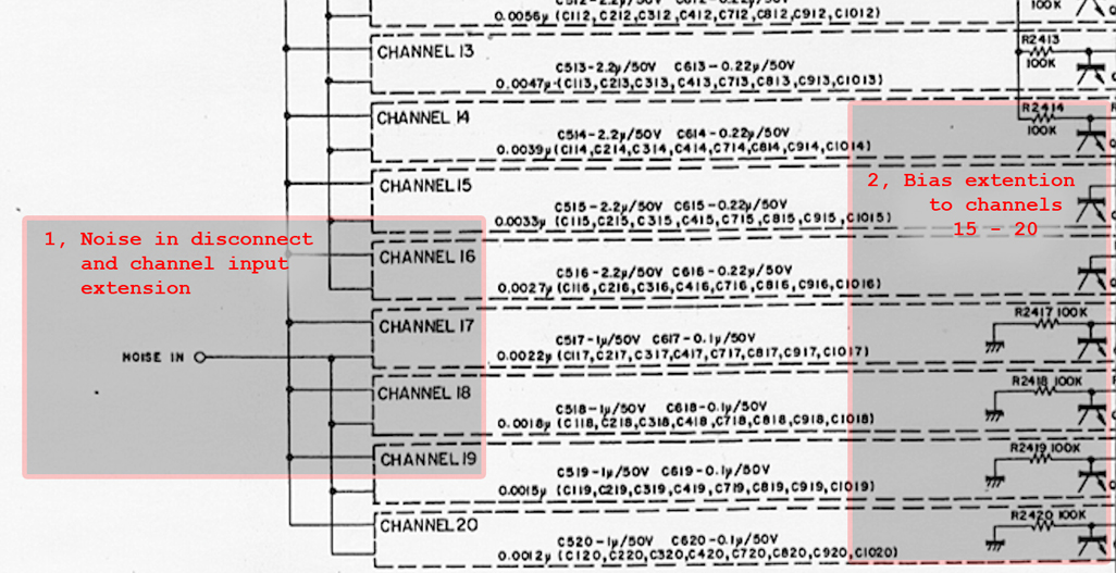
1, There's a quirk in the way the 20 sound generators are treated. Channels 17 to 20 have their carrier input connected NOT to the generator/noise/external mixer, but rather to noise only. The problem here is that this noise signal is attenuated by the generator/noise mixer, resulting in that there will be no carrier to channel 17 to 20 if you turn the generator/noise mixer knob to the generator only position! (which you may often do). Yes, the four highest channels will be quiet! Performing this mod will increase the speech recognition and add the missing edge to the sound.
2, The bias signal for the sound generator does not affect channels 15 - 20. By routing the bias signal to all the channels you get a brighter and more well defined vocoder output as all the channels will behave together. This will also increase the effect of adjusting the bias. This requires adding a few resistors that are not there for channels 15 and 16 and rerouting the 100k resistors for the remaining channels 17-20.
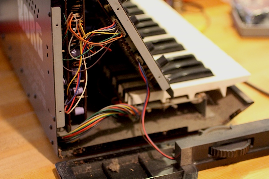
*** On to the dangerous part! ***
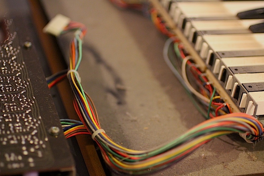
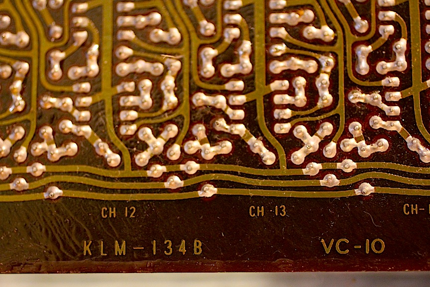
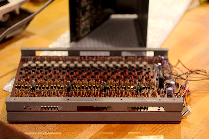
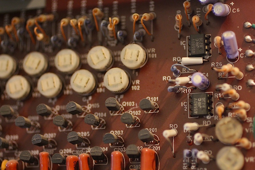
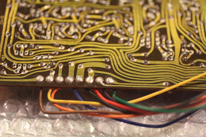
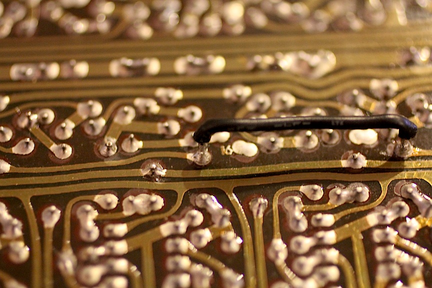
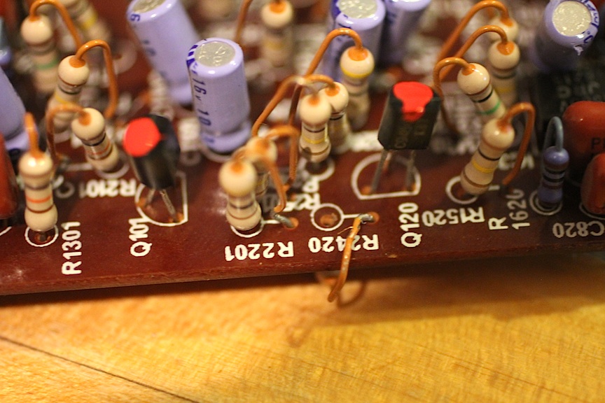
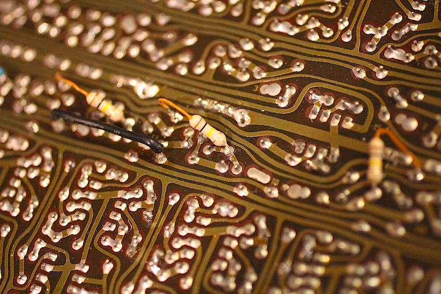
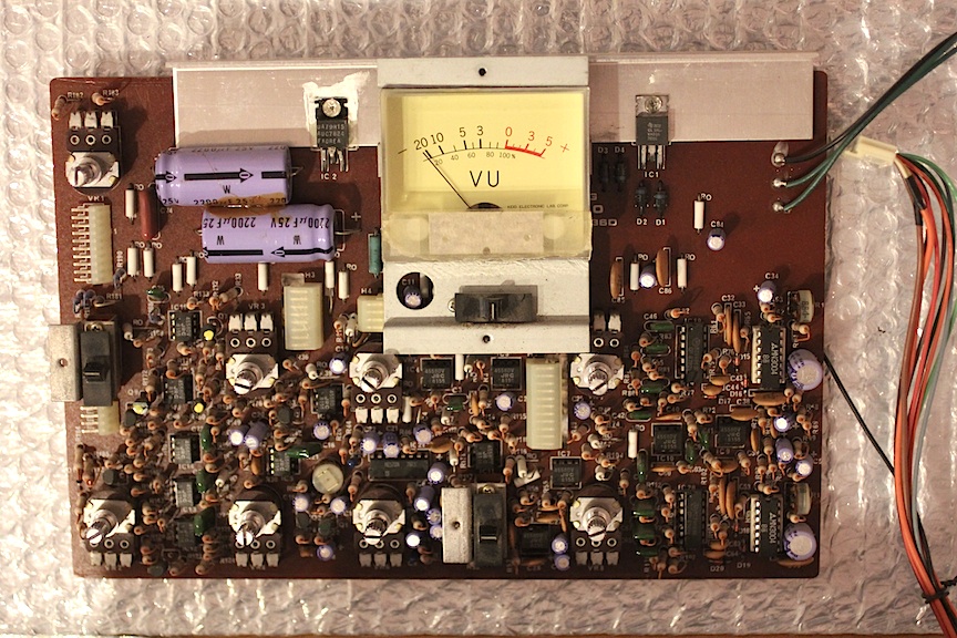
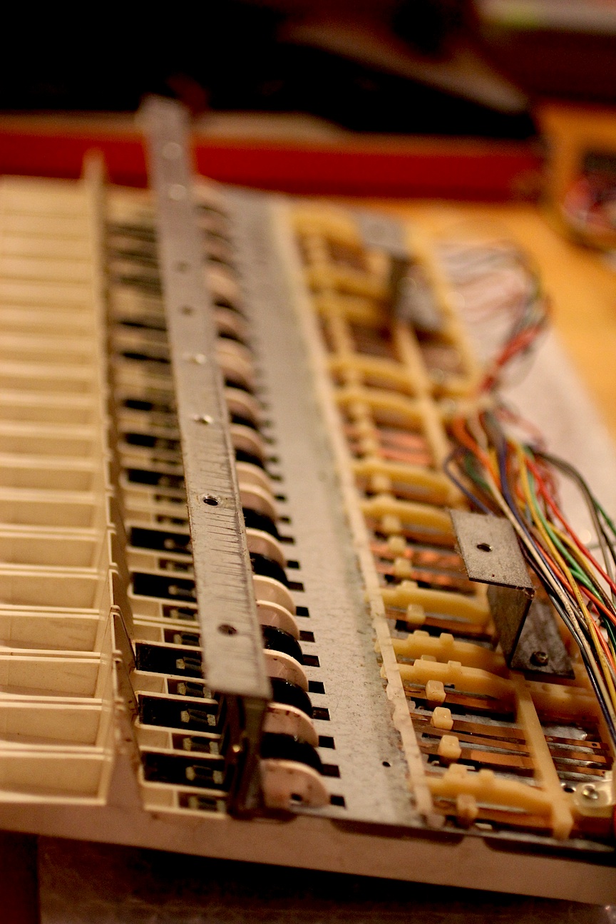
1, The process: Locate and release PCB KLM-134 (the filter board). Locate the wire attached to header H3-1 (noise in). Cut or unsolder the wire. Now locate IC1 on the same board. Find pin 1 and follow the trace to channel 16. Connect from this point to the (now unconnected) corresponding point of channel 17. The channel numbers and the traces pretty easy to locate on the PCB. That one was easy!
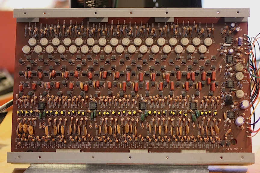
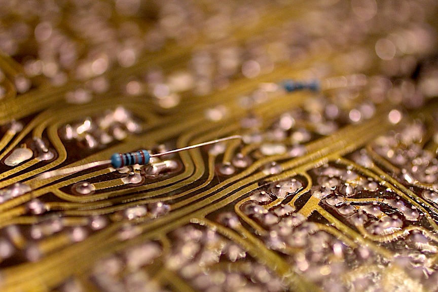
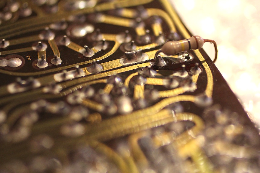
2, The process: On KLM-134, find IC1 pin 7 (bias). Follow this trace to R2414 (100k). Now locate Q115 (channel 15 VCA). Solder a 100k resistor between bias and the base of Q115 (R2315 is connected to the base). Then locate Q116 and solder a 100k resistor between bias and the base of Q116 (R2316 is connected to the base). Channel 17 to 20 already have the 100k resistors you need, but they are connected to ground. Find R2417, R2418, R2419 and R2420. Connect them to bias instead of ground.
Both of these mods sound complicated but are very easily seen in the schematic here:
:::

:::


:::
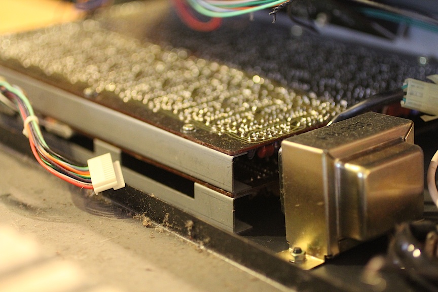
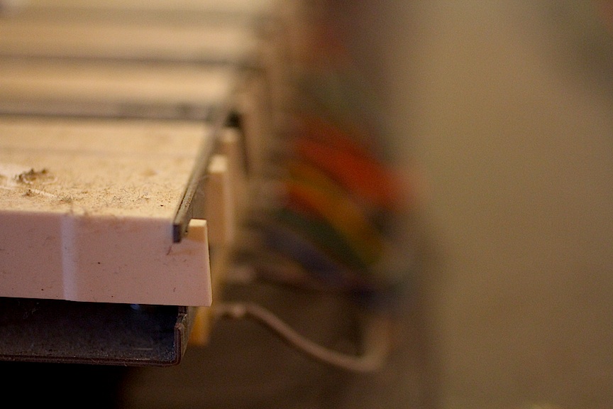
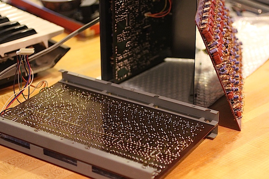
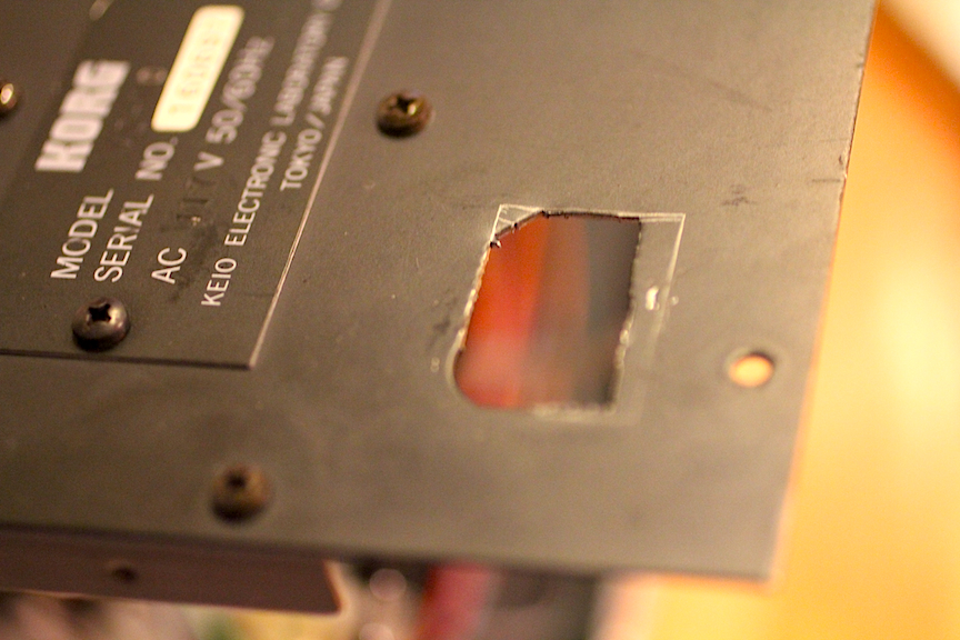
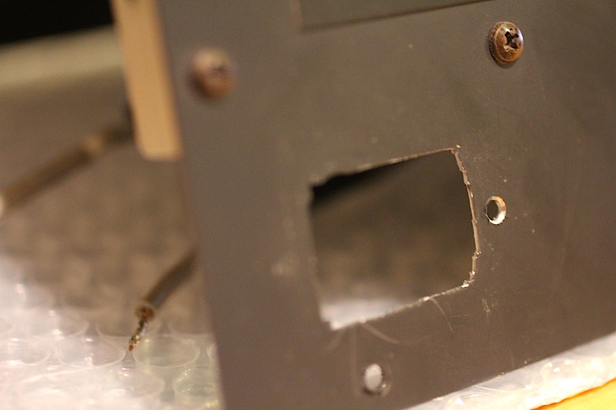
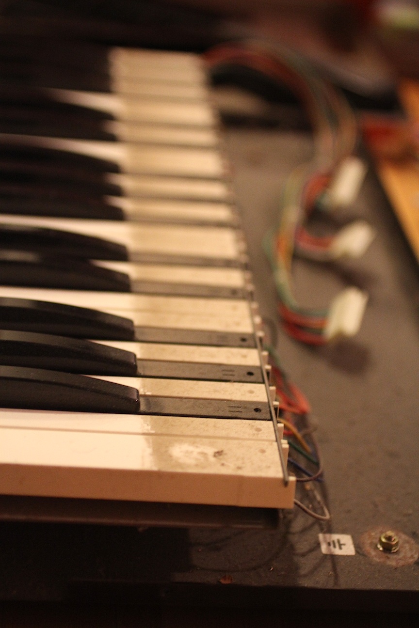
While i was inside the VC-10 i found a few other curious things that i will be discuss in a future post. I had to order more parts to do these bits! It was filthy in there too, so i disassembled the bottom plate and did a thorough clean below the key bed. It's sounding way better to me with the first round of mods. I should have done a before / after recording to reference...
To Be Continued!!
PS: These are the main sites i used for reference, technical info, and modification ideas:
:::

::: IF :::